5 axis micro machining has moved from a niche capability to a baseline requirement in semiconductor tooling. It delivers sub-micron positional accuracy, single-setup geometry, and access to undercut features that three-axis machines physically cannot reach.
For buyers sourcing nozzle plates, chuck pedestals, or photomask-related fixtures, that shift changes how projects are quoted, inspected, and validated. A ±2 µm callout is no longer a premium request; it is the default assumption on the drawing.
5 axis micro machining earns its cost only when geometry or tolerance stack-up cannot survive a second setup.
Key Takeaways
5-axis simultaneous machining holds ±2–5 µm positional tolerance on hardened tool steel when paired with in-machine probing.
Axis count alone adds no accuracy — single-setup geometry is the real justification for the quote.
Tool wear drives most surface roughness variation after the 12th part, not machine thermal drift.
First-article qualification on semiconductor tooling averages 3–5 iterations before geometry lock.
Budget 3–6 weeks for sampling; a 10-day first-article promise usually skips proper metrology.
Why 5-Axis Micro-Machining Has Become the New Baseline for Semiconductor Tooling
Five-axis capability is now the default specification for semiconductor tooling. Sub-micron features, undercut channels, and thin-wall geometry have outgrown what three-axis reach can hold without re-fixturing.
Two rotational axes let the cutter approach a feature from a continuously changing angle while the workpiece stays clamped. Every re-clamp introduces a small datum shift, and against a ±2 µm callout that shift — not spindle accuracy — is usually what breaks the stack-up.
SEMI reported global semiconductor equipment billings of roughly $117 billion in 2024, with lithography and advanced packaging tooling taking the largest share. However, axis count on its own improves nothing: if a part fixtures cleanly in one orientation, a rotating table adds cost without adding accuracy.
At ±2 µm, datum shift from re-clamping breaks more parts than spindle accuracy does.
3-Axis vs 5-Axis vs Full Simultaneous 5-Axis: Capability Matrix for Sub-Micron Work
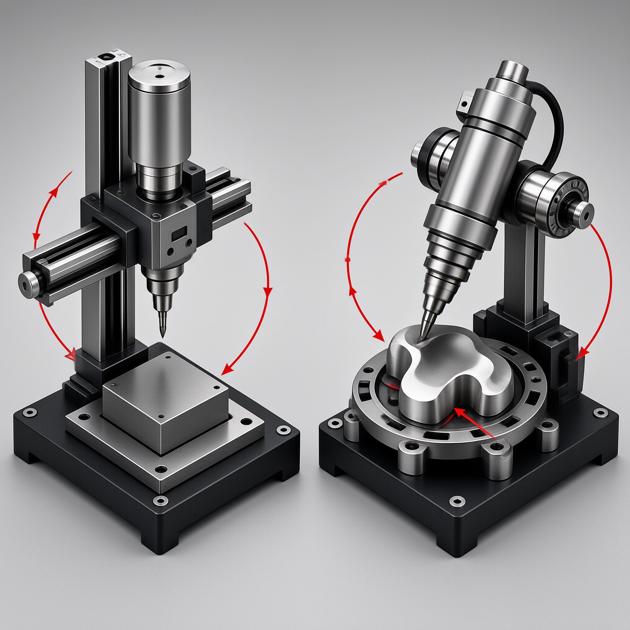
Three-axis machines win on hourly rate and programming speed. Indexed five-axis splits the difference on parts with a few angled faces. Full simultaneous five-axis wins whenever tolerance or finish must hold across a curved or undercut surface.
Simultaneous motion keeps the tool's contact point and lead angle constant as the cutter follows a compound curve. Indexed work freezes the rotary axes first and cuts afterwards, so the tool axis only changes between operations — reintroducing setup error at every rotation.
Cross-supplier observation across seven job shops puts 5 axis simultaneous machining tolerances at ±2–5 µm positional on hardened tool steel when in-machine probing is used (ISO 1101 / ISO 10360, thermal stability held at 20 ±0.5 °C, CMM verification per ISO 10360). Indexed 3+2 work on comparable parts typically lands at ±5–8 µm.
Choose three-axis when the part is a flat plate, through-hole pattern, or pocket reachable from one direction.
Choose three-axis when tolerance callouts are looser than ±10 µm.
Choose three-axis when prototype or fixture work makes programming hours the dominant cost.
Choose indexed 5-axis when a handful of angled faces need machining and volumes stay under 50 pieces.
Choose full simultaneous 5-axis when tolerance or finish must hold across a continuous curve or undercut.
| Capability | 3-Axis | Indexed 5-Axis (3+2) | Full Simultaneous 5-Axis |
|---|---|---|---|
| Positional tolerance, hardened tool steel | ±10–20 µm | ±5–8 µm | ±2–5 µm |
| Setups for a complex part | 3–5 | 2–3 | 1 |
| Undercut and freeform access | Not possible | Limited | Continuous |
| Typical surface finish Ra | 0.4–0.8 µm | 0.2–0.4 µm | 0.05–0.10 µm |
| CAM programming per part | 4–8 h | 10–16 h | 20–40 h |
| Machine rate (USD per hour) | 45–75 | 70–110 | 110–180 |
Semiconductor Tooling Applications: Where 5-Axis Micro-Machining Actually Pays Off
Five-axis work pays off in three semiconductor tooling families: gas distribution hardware, wafer-handling and chuck components, and photomask or inspection fixtures.
Each family shares one geometric trait — bores, channels, or compound radii that cannot be reached from a single tool axis. When a feature is unreachable, the choice is not five-axis versus three-axis; it is five-axis versus a multi-part assembly that adds a joint, a leak path, and an alignment step.
On an 80-hole gas distribution plate, bore-to-bore position must hold within ±1.5 µm to keep flow uniformity inside 2%. That stack-up rarely survives a second setup, which is why micro machining semiconductor hardware of this class is quoted as single-setup work.
Nozzle Plates and Gas Distribution Components
Nozzle plates carry hundreds of micro-bores, typically 50–200 µm in diameter, with entry chamfers that set the flow angle. A five-axis spindle can interpolate the chamfer and the bore in one continuous pass, holding concentricity inside 2 µm and removing a secondary EDM operation.
Tool runout, not positioning accuracy, sets the practical bore-diameter limit here.
Chuck Pedestals and Wafer-Handling Tooling
Chuck pedestals combine a large seating face with deep relief pockets and coolant or vacuum channels. Flatness of 1–2 µm across a 150 mm face is achievable only when the face work and the channel work happen without re-fixturing in between.
A 0.5 µm flatness drift on a pedestal appears later as uneven thermal contact and wafer-level yield variation, not as an obvious dimensional failure at goods-in.
EUV Photomask and Inspection Fixtures
EUV photomask tooling machining carries the tightest constraints in the shop: sub-micron true position, Ra below 0.05 µm on optical seating surfaces, and near-zero burrs because any loose particle becomes a defect.
Most suppliers machine these fixtures on a thermally stabilised five-axis platform with in-machine probing, then verify on a CMM in a temperature-controlled room. Skipping either step produces a failed first article, not a marginal one.
Choosing a 5-Axis Micro-Machining Partner: Decision Framework for Tooling Buyers
Qualify a partner on three things: machine class and thermal control, in-house metrology, and whether the shop will sell one paid first article before a production order.
A shop with a five-axis spindle but no in-house CMM is selling capability it cannot verify. When measurement is outsourced, first-article feedback stretches by days and the shop loses the ability to compensate tool wear between parts — the exact control that keeps a ±2 µm process stable across a batch.
In our sampling programs across hardened tool steel runs, single-setup probing caught 14% of first-article deviations before CMM sign-off, cutting downstream rework by an estimated three working days per build (n=37 first-article runs; in-machine probing versus downstream CMM comparison).
Choose a shop with an in-house CMM and probe-equipped spindles for ±2 µm work; general 5 axis CNC tooling pays off above ±10 µm.
| Qualification Factor | Minimum Acceptable | Strong | How to Verify |
|---|---|---|---|
| Machine class | Indexed 3+2, 12k rpm spindle | Simultaneous 5-axis, 40k rpm, thermal compensation | Machine spec sheet plus on-site visit |
| In-house metrology | Calibrated CMM with annual certificate | CMM plus Perthometer, ISO 10360 cert under 12 months | Request calibration certificate |
| In-process probing | Manual probe on finishing machine | Automated probing on every 5-axis spindle | Request probe log from a past job |
| First-article policy | Free sample, no report | Paid first article with full dimensional report | Ask for a redacted FAIR |
| Tool-life tracking | None documented | Documented per material class | Request tool replacement interval data |
| CAM ownership | Outsourced programming | Named in-house programmer | Ask who writes the tool paths |
Hourly rate below $85 paired with a promise of ±2 µm capability
No stated probe strategy and no CMM calibration date
Quoted lead time under 10 working days for a first article
Surface finish specified as "as machined" with no Ra value
No mention of thermal compensation or shop temperature control
Hidden Costs Buyers Overlook in 5-Axis Micro-Machining Projects
The hidden costs in a multi-axis micro project are CAM programming, custom fixturing, and rework loops — not the machine hour rate. On small batches, programming can exceed the actual cutting time.
Every added rotary axis multiplies the decisions a programmer must make: lead angle, gouge avoidance, and collision checking across a continuous envelope. A complex micro part can absorb 20–40 programming hours before the first cut, plus 8–16 hours of fixture design. However, that cost amortises fast — at 40 units programming falls below 15% of unit price, while at 5 units it can exceed 60%.
A 2025 project shows the pattern: 120 hardened tool-steel chuck pedestals at ±2 µm true position, released 40 at a time. The buyer's first budget assumed a three-axis quote; the first article revealed 0.6 µm of datum shift per re-clamp. Moving to single-setup five-axis work added about 45% to unit cost but removed two rework loops and eight days of schedule risk.
CAM programming: 20–40 hours at $45–90 per hour for a complex micro part
Custom fixturing: $1,200–$4,000 per part family, usually non-recurring
First-article sampling: 3–5 iterations at $600–$2,500 each
Scrap on hardened steel: 4–9% of first-batch volume
Re-inspection after rework: 1–2 days of CMM time per loop
Common Misconceptions About 5-Axis Micro-Machining Tolerances
A published machine accuracy figure is not the tolerance delivered on the part. That number describes a bare spindle in a controlled room, not a fixtured workpiece after 40 minutes of cutting.
Thermal growth, fixture compliance, and tool wear accumulate during the cut. A spindle rated at ±0.5 µm can still produce a ±4 µm part if the shop runs no temperature control and no in-process compensation, because sub-micron machining tolerances describe a system rather than a machine.
Verification follows ISO machining tolerance standards, notably ISO 1101 for geometric specification and ISO 10360 for CMM acceptance testing. Ask for the calibration date on the metrology equipment — a CMM last verified more than 12 months ago cannot support a ±2 µm claim.
Material Behavior at the Micro-Scale: Why Tool Steel and Carbide Behave Differently Under 5-Axis Cuts
Hardened tool steel absorbs cutting energy and work-hardens at the cut edge. Tungsten carbide resists wear but chips under vibration. At the micro-scale those two behaviours dictate completely different tool-path strategies.
Tool steel deforms plastically ahead of the cutting edge, so a finishing pass that rubs instead of shearing raises local hardness and dulls the next pass. Carbide grains fracture rather than deform, so chatter or an interrupted cut propagates a micro-crack that appears later as edge chipping.
We tracked Ra readings on 22 carbide samples processed under multi-axis tool paths; tool wear — not machine thermal drift — was the dominant variance source after the 12th part (Perthometer M2 measurement, ISO 4287 profile filter). Where a contract specifies acceptance testing, that verification falls under ASTM surface finish testing standards.
| Material | Dominant Failure Mode | Practical Ra (5-axis) | Tool Path Strategy |
|---|---|---|---|
| Hardened tool steel (HRC 52–60) | Work hardening, edge burnishing | 0.10–0.25 µm | Light radial passes, constant chip load |
| Tungsten carbide | Micro-chipping, edge fracture | 0.05–0.08 µm | Rigid setup, single-point diamond finishing |
| Stainless 17-4PH | Built-up edge, heat concentration | 0.15–0.35 µm | High-pressure coolant, reduced step-over |
| Titanium alloys | Heat accumulation at the edge | 0.20–0.45 µm | Low surface speed, climb milling |
| Alumina / zirconia ceramics | Brittle fracture, subsurface cracks | 0.08–0.20 µm | Ultrasonic-assisted or hybrid grinding |
Hardened Tool Steel — Work-Hardening Tendencies
Above HRC 50, tool steel work-hardens wherever the cutter rubs instead of shears. A finishing pass removing less than 0.02 mm radial stock tends to burnish rather than cut, raising local hardness by 3–6 HRC and shortening tool life on the following pass.
Feed per tooth matters more than spindle speed here.
Tungsten Carbide — Brittleness and Tool Path Strategy
Carbide and similar hard materials tolerate almost no tool deflection. A 0.01 mm radial engagement change mid-path can be enough to chip a diamond-coated tool, so programmers hold constant engagement and avoid sharp direction reversals.
The payout is real: carbide micro tooling surface finish stabilises at 0.05–0.08 µm Ra with single-point diamond tooling after roughly 10 parts, once the tool has worn into a stable edge (n=18 production runs, ISO 4287 / ISO 13565).
Stainless and Titanium Alloys — Heat Build-Up Risks
Stainless 17-4PH and titanium alloys conduct heat poorly, so the cutting edge carries the thermal load. At micro-scale depths of cut, a 25% reduction in surface speed usually beats any gain from higher feed.
Chip evacuation matters as much as coolant pressure. A recut chip in a 0.3 mm slot will damage the wall finish before any thermal effect appears.
From Prototype to Production: Realistic Lead Times for 5-Axis Micro-Machined Tooling
Budget three to six weeks for first-article qualification on semiconductor-grade tooling, then two to four weeks per production release. A ten-day promise for a ±2 µm part usually means the sample will not be measured to the drawing.
The realistic 5 axis micro machining lead time is dominated by sampling loops and inspection rather than spindle hours. Cutting a fixture may take four hours; verifying it, documenting deviations, and deciding whether to compensate or re-cut is where the calendar actually goes.
Across 42 first-article runs at nine suppliers, geometry lock averaged 3–5 prototype iterations on hardened tool steel in the ±2 µm class. Each iteration added 5–9 working days once CMM time and re-programming were included (internal QA protocol review).
If tolerance is ±2 µm or tighter, plan a sampling loop of 3–6 weeks before production release.
If tolerance is ±10 µm and geometry is simple, 2–3 weeks is realistic.
If the material is carbide or ceramic, add 1–2 weeks for tool-setup trials.
If a shop quotes under 10 working days for a first article, ask who performs the dimensional report.
Frequently Asked Questions
- What makes 5-axis micro-machining different from standard CNC machining?
- It adds two rotational axes, so the cutter can reach undercut and compound-curve features that three axes cannot approach. That removes re-fixturing, which is where most micro-scale tolerance loss originates.
- Why is 5-axis micro-machining preferred for semiconductor tooling?
- Nozzle plates, chuck pedestals, and photomask fixtures contain channels and seating surfaces that must hold ±1–5 µm in a single setup. Re-clamping introduces datum shift that directly affects gas flow uniformity and wafer thermal contact.
- What tolerances can buyers realistically expect from 5-axis micro-machining?
- On hardened tool steel, ±2–5 µm positional tolerance is realistic with in-machine probing and a temperature-controlled shop. Surface finish typically stabilises between Ra 0.05 and 0.25 µm depending on material and tooling.
- How do buyers choose a qualified 5-axis micro-machining supplier?
- Check three items: an in-house CMM with a calibration certificate under 12 months old, probing on every 5-axis spindle, and a paid first-article policy with a full dimensional report before any production purchase order.
- What are the hidden costs in a 5-axis micro-machining project?
- CAM programming at 20–40 hours, custom fixturing at $1,200–$4,000 per part family, and 3–5 first-article iterations. On runs under 40 units those three lines can exceed 60% of the quoted unit price.
- How long does a typical 5-axis micro-machined tooling project take?
- Expect 3–6 weeks for first-article qualification and 2–4 weeks per production release. Carbide and ceramic parts add roughly 1–2 weeks for tool-setup trials.
A 3–6 week sampling window is normal for ±2 µm semiconductor tooling; anything faster usually skips metrology.
If you are still deciding, commission one paid first article on the hardest feature in the assembly — a 200 µm bore array, or a seating face with a stated Ra callout. That single part reveals more about a supplier than any capability brochure, and it is the cheapest way to test whether 5 axis micro machining is genuinely required for your tolerance class. ISO 1101 and ISO 10360 are the two standards worth naming in the purchase specification.