Liquid Cooling vs Immersion Cooling: An Engineering Breakdown for High-Density Datacenters & Power Electronics
Quick Answer for Thermal Architects & Infrastructure Engineers: When conducting an engineering evaluation of liquid cooling vs immersion cooling for next-generation compute, the choice hinges on balancing heat flux capability against operational maintainability. While two-phase immersion cooling and single-phase immersion provide high theoretical heat capture by submerging entire server blades, their commercial adoption is bottlenecked by catastrophic fluid costs ($/liter), aggressive PFAS environmental bans, complex dielectric fluid maintenance, and voided OEM warranties. In contrast, direct-to-chip liquid cooling utilizing a precision-machined microchannel cold plate remains the pragmatic, dominant architecture for modern 800Wâ1200W+ processors (e.g., NVIDIA H100/B200 and AI ASICs). Direct-to-chip integrates seamlessly into standard 19-inch / OCP ORv3 racks, optimizes facility datacenter PUE to 1.05â1.12, preserves standard hot-swappable node serviceability, and delivers far lower TCO through specialized custom cold plate manufacturing with vacuum-brazed, zero-leak reliability.
1. Introduction: The Silicon Thermal Wall & The Death of Air Cooling
The semiconductor industry has officially breached the thermodynamic limits of forced-convection air cooling.
Across modern enterprise compute, hyperscale cloud clusters, and high-frequency trading (HFT) infrastructure, thermal design power (TDP) per socket has escalated dramatically:
- Enterprise CPUs (AMD EPYC⢠9004/9005, Intel® Xeon® 6) consistently push past 350W to 500W TDP.
- AI/ML accelerator packages (NVIDIA H100/H200 SXM5, Blackwell B200, AMD Instinct⢠MI300X) operate at 700W to 1000W+, with localized hot-spot heat fluxes frequently exceeding 100 W/cm² to 150 W/cm² over the compute dies and High Bandwidth Memory (HBM3e) stacks.
- Next-generation multi-die packaging (chiplets) creates severe non-uniform thermal dissipation profiles, where delta-T ($\Delta T$) across adjacent silicon dies must be kept under 5°Câ8°C to prevent thermal-stress-induced physical delamination and clock throttling.
At heat flux levels beyond $80\text{ W/cm}^2$, forced-air cooling faces insurmountable physical constraints:
- Acoustic and Parasitic Pumping Limits: Server chassis fans must spin at 15,000â25,000 RPM, consuming up to 15%â20% of total server power solely to overcome heatsink fin-density pressure drops, while producing noise levels surpassing 85â90 dBA.
- Thermal Resistance Bottleneck: Even with vapor chambers and ultra-dense skived copper fin arrays, conductive-convective thermal resistance ($R_{th, junction-to-ambient}) cannot be driven below 0.08\text{ K/W}, causing junction temperatures (T_j$) to overshoot maximum safe operating limits ($85^\circ\text{C}-105^\circ\text{C}) under ambient datacenter air (25^\circ\text{C}-35^\circ\text{C}$).
To prevent catastrophic thermal throttling, hardware architects must transition to liquid cooling media. The volumetric heat capacity of water is roughly 3,500 times greater than that of ambient air ($C_v \approx 4.184\text{ J/(cm}^3\cdot\text{K)} vs. 0.0012\text{ J/(cm}^3\cdot\text{K)}$), fundamentally resetting the heat removal equation.
However, deciding how to apply liquidâvia Direct-to-Chip (D2C) cold plates or full-immersion bathsârepresents one of the most critical structural and capital expenditure decisions in modern infrastructure engineering.
2. Defining the Two Paradigms
Direct-to-Chip (D2C) Cold Plate
- Chassis: Standard 19" EIA / OCP ORv3 horizontal rackmount sleds.
- Fluid Loop: Closed-loop treated water-glycol (PGW/EGW) delivered via blind-mate QDC couplings and internal manifolds directly to die-mounted microchannel cold plates.
- Targeting: 100% focused on primary thermal bottlenecks (GPUs, CPUs, HBM, VRMs) while chassis airflow handles low-power peripheral components.
Full Submersion Immersion Cooling
- Chassis: Horizontal floor-mounted open bath or hermetically sealed vapor tank.
- Fluid Loop: Bulk non-conductive dielectric fluid (hydrocarbon oil or fluorochemical PFAS).
- Targeting: Total board submersion without chassis fans; heat radiates from every active/passive surface into the surrounding liquid bath.
Direct-to-Chip (D2C) Liquid Cooling (Cold Plate Architecture)
In D2C architectures, heat is removed right at the primary thermal bottlenecks (GPUs, CPUs, high-load memory modules, and power VRMs). High-conductivity metal heat exchangersâcold platesâare mechanically clamped directly over the integrated heat spreader (IHS) or bare silicon dies via high-performance thermal interface materials (TIMs, such as phase change materials or indium foil).
- Coolant Loop: Treated liquid (typically Deionized Water with corrosion/antimicrobial inhibitors like Propylene Glycol Water, PGW25/PGW50) is pumped through internal microchannels inside the cold plate, capturing heat via forced convective single-phase flow.
- Form Factor Compatibility: The servers remain configured in traditional horizontal rackmount form factors (1U, 2U, or OCP Open Rack v3). Secondary heat sources (low-power NICs, SSDs, capacitors) can either be chilled by secondary mini-cold plates or handled by low-velocity auxiliary chassis airflow (hybrid air-liquid cooling).
- Cooling Distribution Unit (CDU): Fluid routing is managed through quick-disconnect couplings (QDCs) and rack manifolds connected to an in-row or centralized CDU.
Immersion Cooling (Single-Phase & Two-Phase)
Immersion cooling eliminates targeted heatsinks and cold plates entirely by submerging all active electronics directly into an electrically non-conductive, dielectric fluid.
- Single-Phase Immersion (1PIC): Servers are mounted vertically inside horizontal "baths" or sealed chassis filled with hydrocarbon-based oils or synthetic fluids. The fluid remains in a liquid state throughout the cycle, circulated by pumps through external heat exchangers.
- Two-Phase Immersion (2PIC): Servers are submerged in specialized low-boiling-point fluorochemical dielectric liquids (e.g., boiling at $50^\circ\text{C}-60^\circ\text{C}$). Heat from the silicon causes the liquid to boil directly on the chip surface, creating vapor bubbles that rise to a water-cooled condenser coil mounted in the tank lid, condensing back into liquid droplets that fall back into the reservoir.
3. Key Engineering Comparison Matrix
The table below contrasts both approaches across the exact mechanical, thermal, operational, and capital metrics evaluated by thermal architects.
| Metric | Direct-to-Chip (D2C) Cold Plate | Single-Phase Immersion (1PIC) | Two-Phase Immersion (2PIC) |
|---|---|---|---|
| Max Chip Heat Flux Handling | Up to 150+ W/cm² (Optimized Microchannel) | ~40 â 60 W/cm² (Natural/Low Forced Convection) | Up to 120 â 150+ W/cm² (Boiling Heat Transfer) |
| Thermal Resistance ($R_{th, j-f}) | 0.02 â 0.05 K/W | 0.08 â 0.15 K/W | 0.03 â 0.06 K/W |
| Typical Facility PUE | 1.05 â 1.15 | 1.03 â 1.08 | 1.02 â 1.05 |
| Coolant Fluid Medium | Water-Glycol mix (PGW/EGW) or pure DI Water | Synthetic Hydrocarbon or Polyalphaolefin (PAO) | Fluorochemicals (PFAS-based: e.g., FK-5-1-12) |
| Coolant Cost per Liter | <2 / Liter | 15 â 30 / Liter | 250 â 400+ / Liter |
| Coolant Replacement / Evaporation | Negligible (Closed hermetic loop) | Low (Fluid drag-out during pulls) | High risk (10,000+ loss/year from seal micro-leaks) |
| Chassis / Facility Retrofit | Drop-in Compatible with standard 19" / OCP racks | Requires tank beds, overhead cranes, floor rebuild | Specialized vapor-tight pressure tanks, condenser infrastructure |
| Floor Weight Loading | Standard floor ratings (~1,000â1,500 kg/rack) | Requires reinforced floors (>2,500 kg/tank) | Heavy structural reinforcement required |
| Maintenance Ergonomics | Hot-swappable blade sleds via dry-break QDCs | "Crane and Drip pan" process; messy oil cleanup | Critical seal break risks; expensive vapor escape |
| Component Warranty & Compatibility | Full OEM support (standard board components) | Voids many warranties; dissolves some rubbers/TIMs | Strips thermal pastes; dissolves certain capacitors |
| Regulatory & Environmental Risk | Zero PFAS exposure; standard wastewater safe | High disposal cost for spent hydrocarbons | Severe (Global phase-out of PFAS/forever chemicals) |
4. The Practical Reality of Immersion Cooling: Why Industry Wide-Scale Adoption Has Stalled
Despite enthusiastic marketing claims regarding record-low PUE numbers (<1.05), immersion cooling routinely encounters severe operational and supply-chain friction when moved from pilot lab testing into commercial production environments.
4.1 The Dielectric Fluid Economic & Regulatory Trap
In single-phase systems, fluid cost is non-trivial, but in two-phase immersion cooling (2PIC), fluid economics become prohibitive:
- Specialized fluorinated fluids command prices between 250 to $450 per liter. A single 50kW compute tank can require 400 to 600 liters of fluidârepresenting $100,000 to $250,000 in fluid alone per tank.
- PFAS Regulatory Bans: Regulatory bodies worldwide (EU REACH restrictions, US EPA rules) are systematically outlawing per- and polyfluoroalkyl substances (PFAS) due to biological persistence. In late 2022, 3Mâthe dominant global producer of Fluorinert⢠and Novec⢠dielectric fluidsâannounced an absolute exit from all PFAS fluid manufacturing by the end of 2025. This has thrown the future supply chain of two-phase cooling into complete disarray, leaving datacenters exposed to fluid obsolescence and runaway maintenance costs.
- Evaporative Loss: Despite sophisticated vapor gaskets, every maintenance opening of a 2PIC tank releases vapor. At hundreds of dollars per kilogram, even minor degassing or vapor-seal degradation represents tens of thousands of dollars in unbudgeted annual operational expenses.
4.2 Dielectric Fluid Maintenance & Ergonomics: The "Dipping and Dripping" Problem
Datacenter operations thrive on Mean Time to Repair (MTTR) measured in minutes. However, the realities of dielectric fluid maintenance introduce severe friction into daily service tasks:
- With direct-to-chip liquid cooling, a failed compute blade is isolated using zero-drip blind-mate quick disconnects, slid out of the rack horizontally, serviced on a clean antistatic bench, and replaced without affecting neighbor sleds.
- In immersion tanks, pulling a single blade requires an overhead motorized gantry hoist. As the blade is lifted from the horizontal tank, it must hang in a "drip rack" for 30 to 60 minutes while hydrocarbon oil drains off the components. The technician must then work with oil-coated heatsinks, PCBs, and connectors, introducing slip hazards, specialized solvent wash requirements, and high contamination risks.
4.3 Material Incompatibility & High-Frequency Signal Integrity
Submerging a motherboard in fluid affects more than just temperature:
- Material Leaching: Certain dielectric fluids chemically leach plasticizers from ribbon cables, dissolve elastomer gaskets, and strip adhesives from optical transceivers.
- High-Speed Signal Degradation: Dielectric fluid changes the permittivity ($\epsilon_r) surrounding high-speed PCIe 5.0/6.0 and 800G Ethernet differential traces. Trace impedances designed for 85\text{ }\Omega in air drop significantly when flooded with dielectric fluids (\epsilon_r \approx 1.8 - 2.2$), inducing signal reflection, eye-diagram closure, and increased bit error rates (BER) unless motherboards are custom-designed from scratch for immersion.
5. Why Direct-to-Chip (D2C) Microchannel Cooling Dominates High-Density Compute
For the vast majority of hyperscalers, colocation providers, and high-density enterprise environments, Direct-to-Chip (D2C) liquid cooling represents the absolute engineering sweet spot between thermal efficacy and pragmatic operability.
5.1 Thermal Density Handling Beyond 1,000 Watts
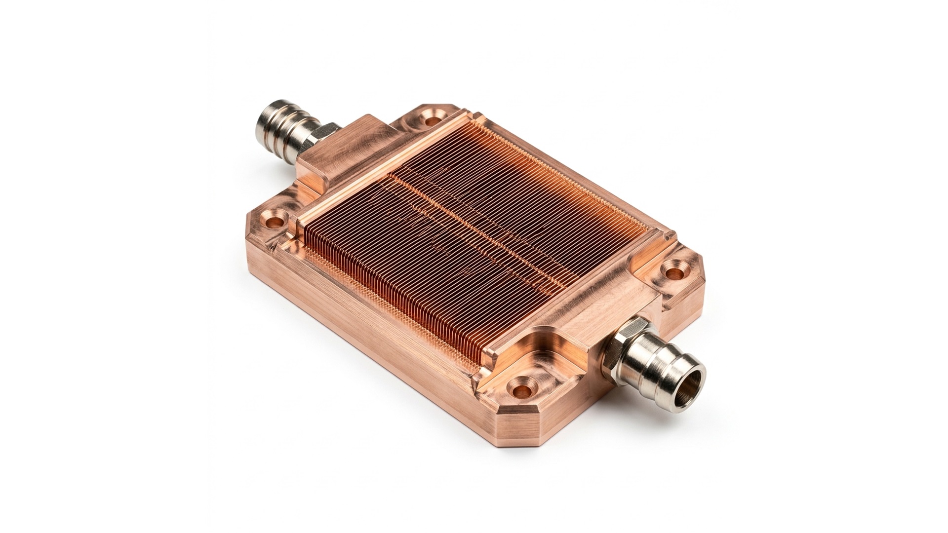
Advanced microchannel cold plates bypass bulk-fluid convection barriers by driving coolant through micron-scale fin arrays directly above the heat source.
By shrinking fin width to $150\text{ }\mu\text{m} - 250\text{ }\mu\text{m}$ and fin channels to $200\text{ }\mu\text{m} with aspect ratios exceeding 10:1$ to $15:1, the wet surface area is multiplied by an order of magnitude. The laminar boundary layer is continuously disrupted, achieving convective heat transfer coefficients (h$) exceeding:
This performance allows cold plates to comfortably keep modern 1,000W+ GPUs below $65^\circ\text{C} junction temperature using warm facility water supply loops (32^\circ\text{C}-45^\circ\text{C}$ ASHRAE W3/W4 standards), eliminating the need for energy-hungry chillers and securing enterprise PUE ratings of 1.05 to 1.10.
5.2 Capital Investment & Brownfield Retrofittability
Unlike immersion cooling, which requires tearing up datacenter raised floors, replacing concrete slabs to bear metric-ton liquid tanks, and throwing away existing hot-aisle/cold-aisle containment:
- D2C cold plates mount inside standard form-factor servers.
- Facilities can execute incremental brownfield rollouts: retrofitting 5 to 10 high-density AI racks inside an existing air-cooled datacenter by simply wheeling in row-based CDUs.
- Facility capital expenditure (CAPEX) per megawatt of compute deployed is typically 30% to 55% lower for D2C than for greenfield immersion installations.
6. Design for Manufacturability (DFM) Insights: Custom Cold Plate Manufacturing at Scale
Building a cold plate that performs on a simulation model is straightforward; executing custom cold plate manufacturing for tens of thousands of units that survive 7 to 10 years of 24/7 continuous operation inside multi-million-dollar AI supercomputers requires ruthless precision manufacturing standards.
At Altus Precision, our engineering and fabrication workflows address the primary failure modes of high-density liquid cooling:
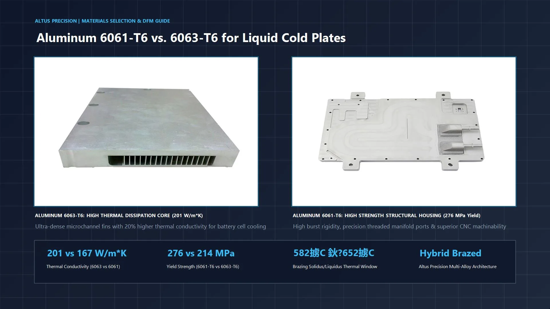
6.1 Metallurgy: C10100 Oxygen-Free Electronic (OFE) Copper
Standard commercial copper (such as C11000 ETP) contains trace oxygen that can cause hydrogen embrittlement during high-temperature brazing cycles, creating microscopic boundary voids that invite pinhole leaks.
Altus Precision machines cold plate bases from certified C10100 / C10200 Oxygen-Free Electronic Copper (thermal conductivity $\lambda \ge 391\text{ W/(m}\cdot\text{K)}$).
- Base plates undergo precision multi-axis CNC surface machining to achieve a surface flatness specification of $<0.01\text{ mm} across the die contact area and surface roughness of Ra < 0.2\text{ }\mu\text{m}.
- This eliminates microscopic air gaps between the cold plate and bare silicon dies, minimizing interfacial contact resistance (R_{interface}) without requiring excessive clamping pressures that risk cracking fragile 2.5D/3D silicon packages.
6.2 Microchannel Geometry vs. Pressure Drop (\Delta P) Tradeoff
A frequent design flaw in third-party cold plates is over-optimizing for thermal surface area while creating unacceptable hydraulic resistance. A pressure drop exceeding 50\text{ kPa} across a single cold plate creates severe system-level drawbacks: it overburdens the CDU pump, increases parasitic pumping power, and risks flow imbalance across multi-socket racks.
Our thermal engineering team utilizes CFD-guided internal manifolding with multi-inlet jet impingement profiles:
- Rather than pushing coolant across the entire length of the fin stack, coolant enters through a central slot, impinges perpendicularly on the hottest central silicon area, bifurcates, and exits via parallel return runners.
- This cuts the hydraulic fluid path length in half, reducing overall loop \Delta P$ by 40% to 60% while simultaneously lowering hot-spot temperature gradients.
6.3 Vacuum Brazing vs. Controlled Atmosphere (CAB): The Zero-Flux Imperative
Traditional liquid cooling fabricators frequently employ Controlled Atmosphere Brazing (CAB) using corrosive or non-corrosive chemical fluxes. In high-density datacenter loops, any flux residue is catastrophic: residual flux breaks down over time, flakes off into the fluid stream, clogs microchannels, and initiates localized galvanic pitting.
The Altus Precision Standard: We exclusively deploy High-Vacuum Brazing at pressures ranging from $10^{-5}$ to $10^{-6}\text{ mbar} using nickel-based (BNi) or silver-based active braze alloys:
- 100% Flux-Free: Zero chemical contaminants inside the flow channels.
- Superior Mechanical Strength: Brazed joint shear strengths exceed 180â220 MPa, transforming the cold plate lid and base into a near-monolithic copper component.
- Elimination of Intermetallic Corrosion: High thermal uniformity across the braze chamber prevents void formation, achieving braze coverage rates >98%$ across all sealing ribs.
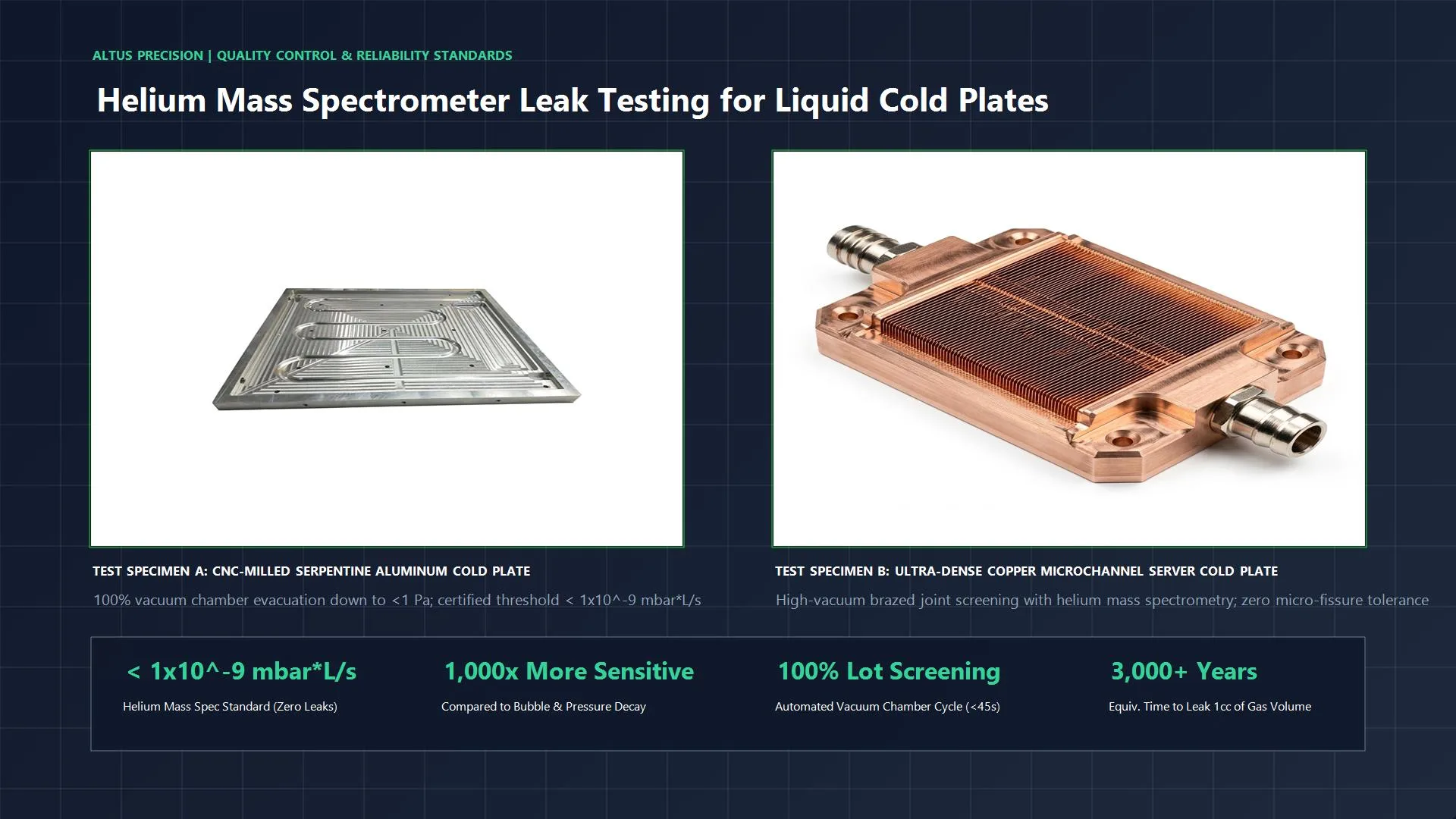
6.4 Zero-Leak Verification: The Helium Mass Spectrometry Standard
Hydrostatic pressure testing (e.g., soaking a plate at 10 bar for 30 minutes) is necessary for burst verification, but completely inadequate for detecting micro-fissures that allow slow fluid migration over years of thermal cycling.
Every Altus Precision custom cold plate undergoes Vacuum Chamber Helium Mass Spectrometer Leak Detection:
- The component is evacuated in a vacuum test chamber down to $<1\text{ Pa}$, pressurized internally with 99.999% pure helium gas, and analyzed.
- We certify leakage rates below:Qleak < 1 × 10⁻⁹ mbar·L/s
- At this threshold, a cold plate would require over 3,000 years to leak a single cubic centimeter of gas, guaranteeing complete hermetic integrity inside mission-critical server environments.
7. Frequently Asked Questions (FAQ)
Q1: At what power density / TDP does air cooling definitively fail and mandate liquid cooling?
Answer: Forced air cooling universally hits an efficiency and acoustic brick wall when individual chip package TDP exceeds 400W to 500W, or when package-level heat flux surpasses $70 - 80\text{ W/cm}^2$. Beyond this threshold, the volume of copper fin stack and airflow CFM required cannot physically fit inside standard 1U, 2U, or 4U rack chassis envelopes. For next-generation hardware like the NVIDIA B200 (1000W TDP) or high-density ASIC clusters, liquid cooling is an absolute physical requirement, not an optional upgrade.
Q2: Can existing standard 19-inch rack datacenters adopt direct-to-chip cooling without structural floor rebuilds?
Answer: Yes. This is one of the primary engineering advantages of D2C liquid cooling. Standard server racks (EIA-310 19-inch or OCP ORv3 21-inch) can be adapted using rack-level manifolds and blind-mate liquid disconnects. Because fluid remains confined within compact internal pipes and cold plates, rack weights remain well within typical datacenter concrete slab ratings (1,000â1,500 kg per rack). In contrast, immersion tanks can weigh 2,500 to 4,000 kg per footprint, requiring seismic anchoring and civil engineering structural floor reinforcement.
Q3: What causes galvanic corrosion in liquid loops, and how does precision cold plate manufacturing mitigate it?
Answer: Galvanic corrosion occurs when dissimilar metals with significantly different electrochemical potentials (such as copper and aluminum) are placed in electrical contact within an electrolyte solution (such as water). The aluminum acts as an anode and rapidly corrodes, creating pinholes and sludging that clogs microchannels. Altus Precision mitigates this risk by offering all-copper wetted flow architectures (C10100/C11000 base + copper cover plates vacuum brazed with BNi/Ag filler) or applying pore-free, electro-less nickel (ENIG) diffusion coatings on wetted aluminum assemblies to eliminate metal-to-liquid ionic transfer.
Q4: How does two-phase immersion compare with two-phase direct-to-chip (evaporative cold plates)?
Answer: Two-phase direct-to-chip cooling utilizes the latent heat of vaporization inside an enclosed, hermetically sealed microchannel cold plate loop rather than boiling open fluid across an entire chassis. While two-phase D2C provides massive heat flux handling ($>200\text{ W/cm}^2), single-phase D2C (water-glycol) paired with optimized microchannel geometries currently satisfies >95%$ of commercial compute demands up to 1200W TDP. This avoids the high operating pressures, vapor recovery complications, and fluid licensing expenses associated with two-phase systems.
8. Conclusion: Strategic Architecture Selection for Thermal Engineers
When evaluating thermal management strategies for modern high-density compute facilities:
- Immersion Cooling remains an intriguing choice for highly specialized edge installations, extreme environmental conditions (e.g., highly dusty, unconditioned ambient sites), or niche research facilities where component longevity, service speed, and fluid replacement costs are secondary to total enclosure isolation.
- Direct-to-Chip (D2C) Liquid Cooling remains the undisputed industrial champion for commercial AI datacenters, hyperscale cloud, and enterprise computing. It combines high thermal performance (handling >1,000W+ per socket), zero-regulatory fluid risk, standard rack architecture compatibility, and lightning-fast node serviceability.
The critical variable in D2C success is not whether liquid cooling worksâit is whether your cold plate manufacturer can deliver the geometric tolerances, metallurgy, and joint hermeticity required to protect mission-critical silicon over a multi-year deployment.
Accelerate Your Thermal Architecture with Altus Precision
Are you designing next-generation cooling systems for high-TDP CPUs, GPUs, or power electronics? Do not let thermal throttling or manufacturing defects compromise your silicon performance.
Altus Precision partners with thermal engineering teams globally to deliver:
- Custom Microchannel Cold Plate Machining: Fin widths down to $0.15\text{ mm}$, aspect ratios up to $15:1, and flatness tolerances <0.01\text{ mm}.
- Flux-Free High-Vacuum Brazing: Monolithic joint strength without chemical contamination.
- 100% Helium Mass Spectrometer Testing: Certified leak rates below 1 \times 10^{-9}\text{ mbar}\cdot\text{L/s}$.
- Complete DFM Analysis: Comprehensive thermal, hydraulic, and structural feedback within 24 hours of CAD submission.
ð Ready to validate your thermal designs?
Submit your STP / CAD drawings to our thermal engineering group today for a comprehensive DFM review and prototype manufacturing proposal:
- Website: altusprecision.com
- Engineering Inquiries:
info@altusprecision.com - Upload CAD for DFM Evaluation: Request Cold Plate DFM Review